Europe
  Türkiye
  United Kingdom
  Global


 0
0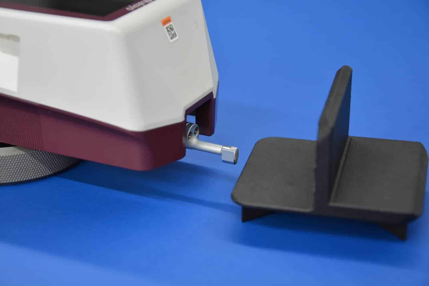
The surface quality of 3D printed parts is not similar for every process and every raw material. It varies greatly depending on the 3D printing technology employed, the printer quality and the build material. The design of the part to be printed and the position and orientation of the part during build also influence the surface quality.
Before choosing an additive manufacturing process, one needs to consider the roughness (measured in most cases in Ra) of the 3D printed parts. For the technologies that use support structures, like fused deposition modeling (FDM), special care needs to be taken since there is a contact point between the support structures and the actual part which has a different surface quality altogether.
Evaluating Surface Roughness of 3D Printing Processes
The surface roughness of a material is basically measured in terms of Ra and Rz values. The R values are usually measured in µm.
In simple terms, Ra can be said as the deviation from the ideal surface plane usually measured in microinches or micrometres (µm). The higher the Ra value, the rougher the surface. The main regulation governing surface roughness is ISO 25178 which measures the surface roughness in terms of Ra and Rz values.

The roughness of a surface depends on a variety of factors, including the design of the part, the manufacturing process used to create it and the manufacturer. Even if you select a 3D printing technology with a supposedly great surface finish, the parts might still present some stepping marks or have a slightly curved surface, causing a decreased surface roughness quality.
How to Measure Surface Roughness in 3D Printing?
To measure the surface roughness of 3D print, the easiest and most accurate way is to use a roughness tester, or “roughness meter”. This instrument measures the roughness of a surface. It is commonly used in manufacturing and engineering applications where the texture and surface finish of a material is critical to the functionality of the end product.
The roughness tester typically consists of a motorized drive unit that moves the stylus across the surface at a constant speed, a transducer that converts the mechanical movement of the stylus into an electrical signal, and a display unit that shows the roughness measurement.
Let us take a look at the surface roughness variations and differences of 3D printed parts according to the technological categories. All the measurements were done in-house and are average. One may find different results with parts printed with a different material or by a different provider.
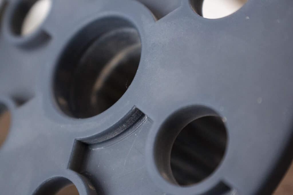
Surface Roughness for Powder Bed Fusion (PBF) Processes
PBF includes technologies like multi jet fusion (MJF), selective laser sintering (SLS) and Direct metal laser sintering (DMLS) where the build materials are usually polymers and metal powders. This powdered build material is fused together to form the part as per the CAD design with the help of infrared in MJF and laser in SLS and DMLS.
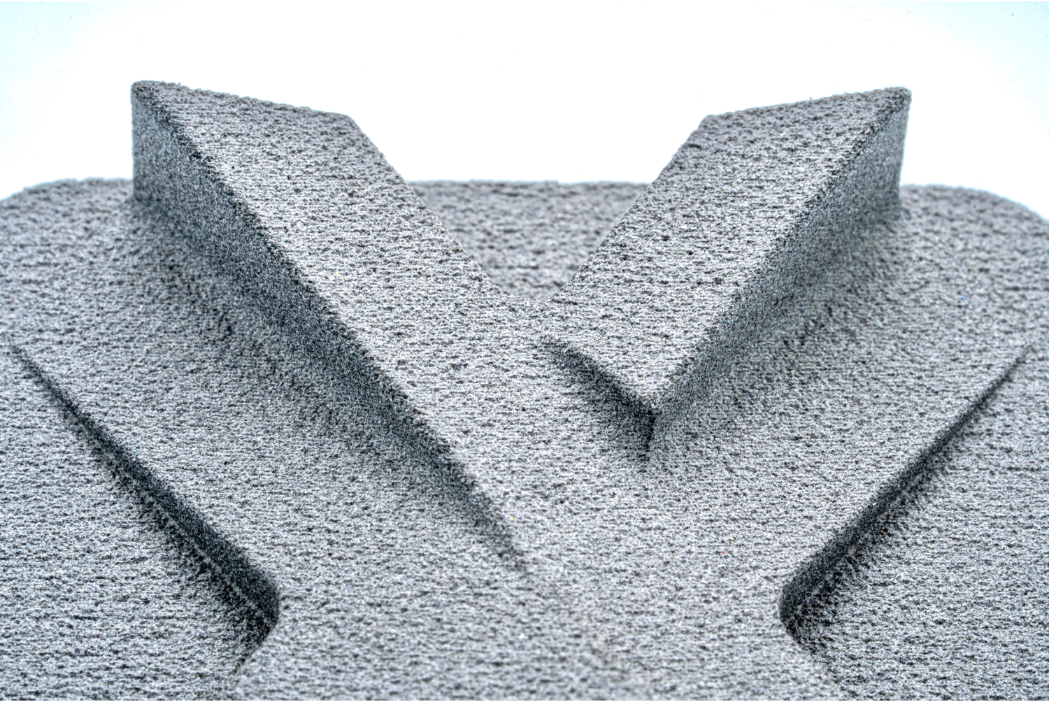
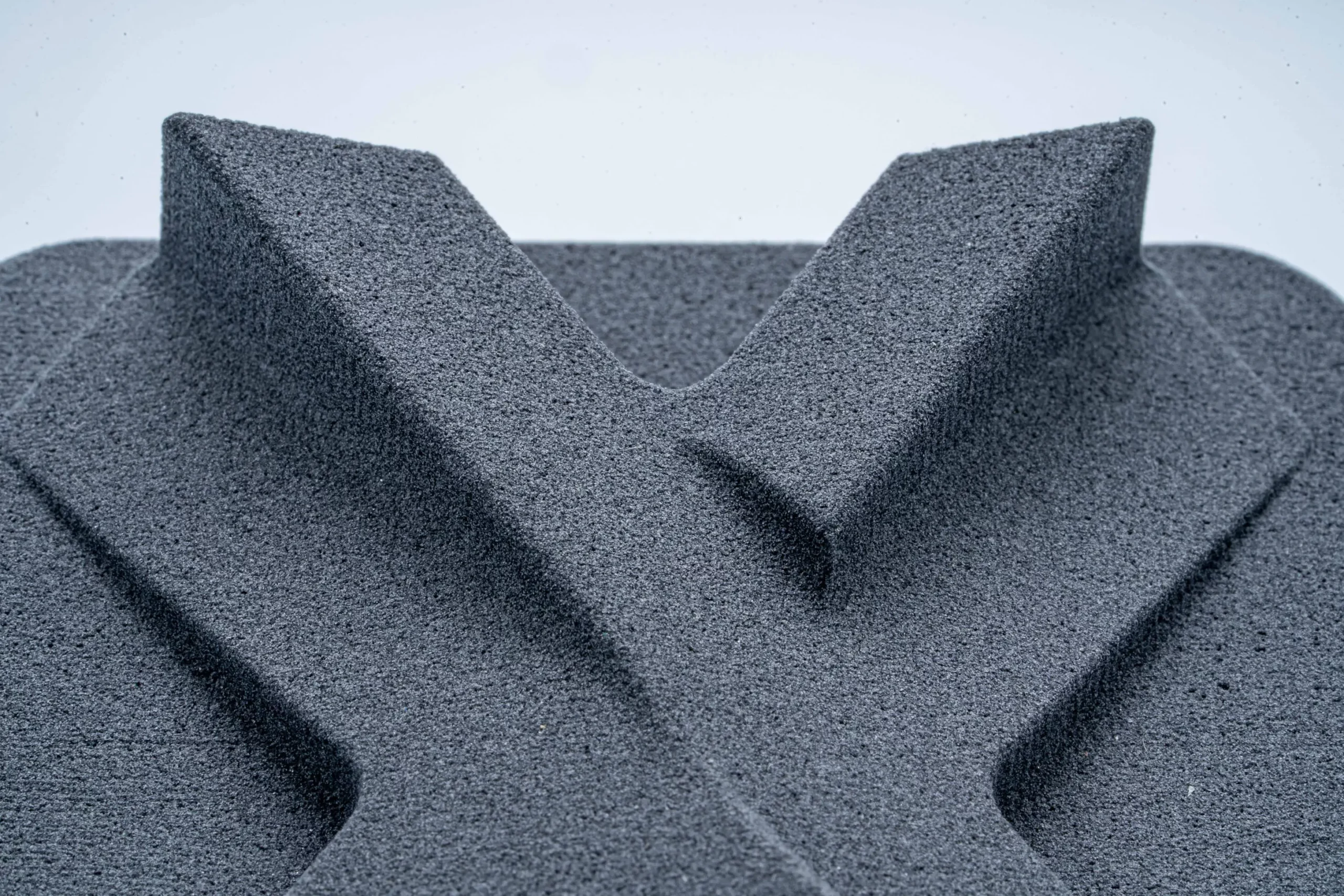
The surface texture is matte and is not as smooth as SLA but it doesn’t require support structures. Holes and pores can occur on the surface, depending on the size of the powder grain. Reused powder will cause more nonuniformities on the surface.
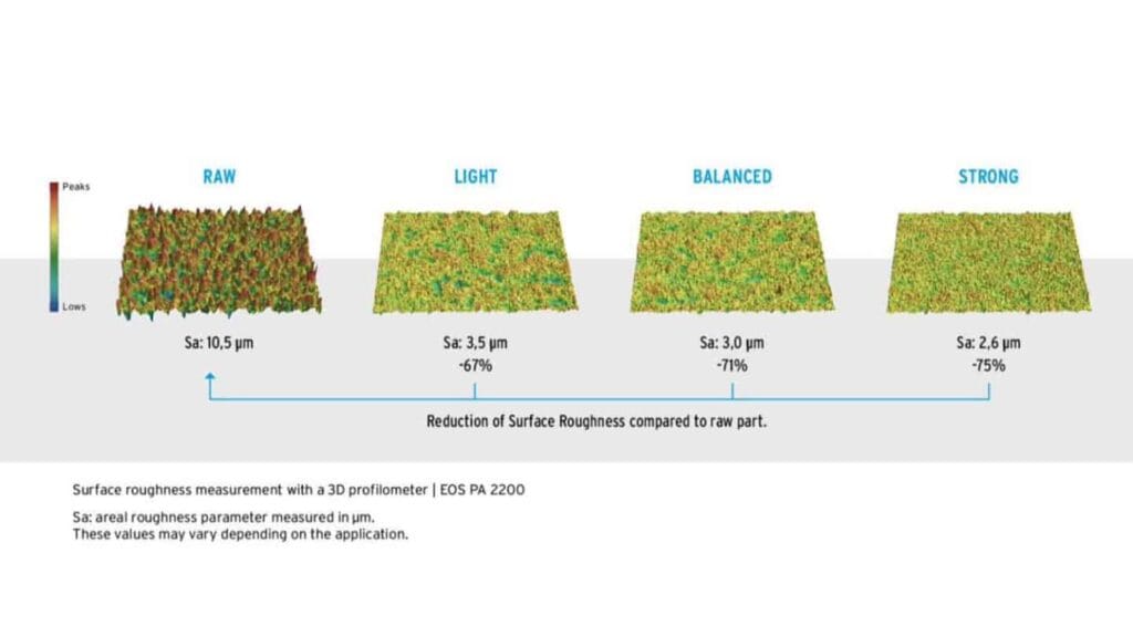
A completely smooth, glass-like surface cannot be obtained on the printed surfaces, even after heavy treatment like blasting or sanding. However, the MJF process produces a less porous surface compared to SLS and has a smoother texture comparatively.
For PBF technologies, the cheap and ideal way of smoothing the surface is using sand paper. The other processes include grinding, sand or bead blasting and tumbling. Grinding and blasting will have little impact on tolerances and dimensions. Nevertheless, tumbling is an efficient process but is much slower compared to other surface finish methods.
In SLS, a near perfect poreless surface can only be achieved with vacuum infusions or a multi-stage process of surface filling and multiple grinding.
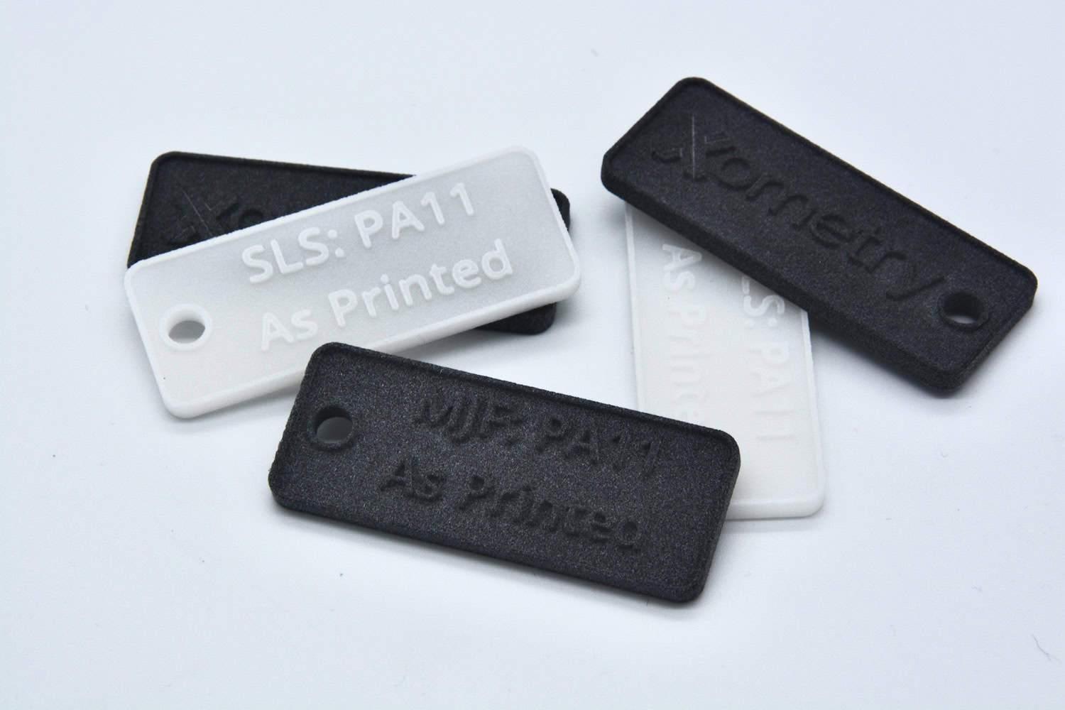
Surface Roughness of SLS 3D Printed Parts
The table below shows the variation of the measured surface roughness between as printed parts, and parts after a surface finish:
| Material | Surface finish | Ra | Rz |
| Alumide® / PA 12 filled with aluminium | As printed | 8 µm | 50.1 µm |
| PA 12 | Bead blasted | 4.5 µm | 31.6 µm |
| PA 11 | Dyed black | 7.5 µm | 47.6 µm |
| PA 12 | Media tumbled | 7.1 µm | 45.5 µm |
| PA 12 | Vapour polished + dyed black | 2.5 µm | 19.7 µm |
Surface Roughness of MJF Parts
The table below details Ra and Rz values on both sides for MJF 3D prints:
| Material | Surface finish | Ra | Rz |
| PA 12 | As printed | 10 – 12 µm | 59.9 – 69.4 µm |
| PA 12 | Chemical vapour polished | 4.4 µm | 31.1 µm |
| PA 12 | Dyed black | 5.8 µm | 38.7 µm |
| PA 12 | Spray painted black | 5.5 µm | 37.1 µm |
Hence, surface finishing can substantially reduce the surface roughness and improve the surface properties such as the strength of the overall part by reducing the porosity.
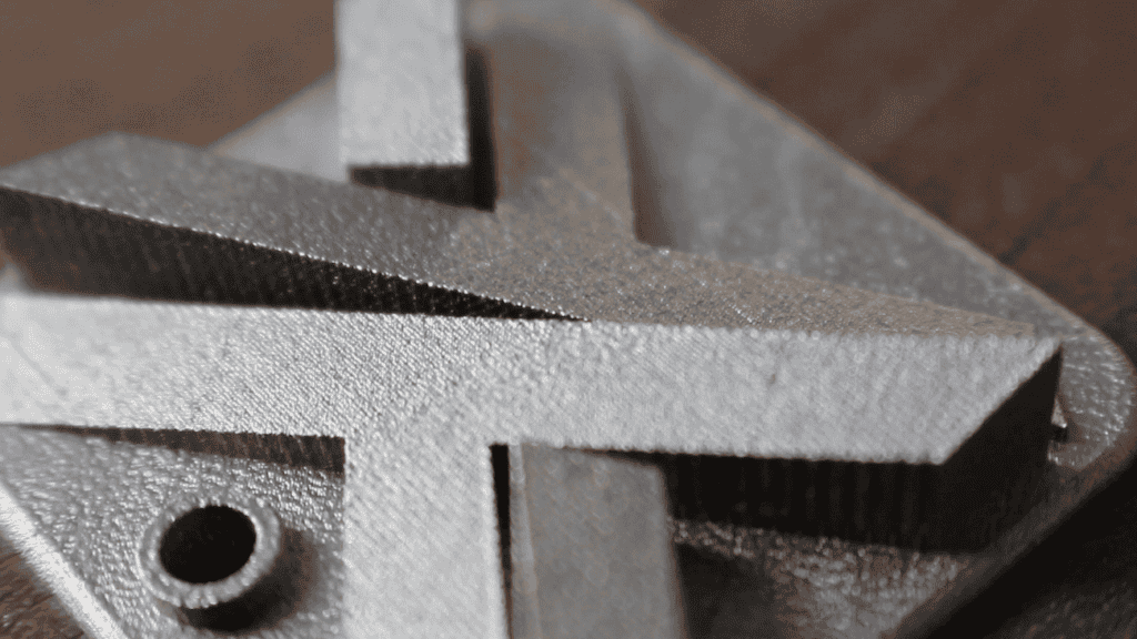
Surface Roughness of DMLS Parts
The table below details Ra and Rz values on both sides for DMLS 3D prints. As a regular practice for metal 3D printed parts, all the parts used for the measurements were bead blasted.
| Material | Surface finish | Ra | Rz |
| Aluminium Al-Si10Mg | Bead blasted | 10-12 µm | 59.9-69.4 µm |
| Stainless Steel 316L | Bead blasted | 6 µm | 39.8 µm |
| Titan Grade 5 | Bead blasted | 5 µm | 34.4 µm |
Surface Roughness for VAT Polymerisation Processes
The most frequently used technologies in this category are stereolithography (SLA) and Carbon DLS (also called DLP – digital light processing). These printing processes make use of a liquid polymer build material which, on exposure to the laser beam, hardens, producing the shape according to the input design, layer by layer. Since the material used is liquid, these technologies produce rather non-porous 3D printed parts with smooth surfaces.
Nevertheless, both SLA and digital light processing technologies require support structures which have to be removed once the part is 3D printed. And this procedure does have a huge impact on the surface roughness. Indeed, when the support structures are clipped off from the actual part, the roughness at that point becomes uneven and has higher Ra and Rz values.
Surface Roughness of SLA 3D Printed Parts
The table below details Ra and Rz values on both sides for SLA 3D prints:
| Material | Surface finish | Ra | Rz |
| Industrial White, ABS-like | As printed | 1.5 µm | 10.1 µm |
Surface Roughness of Carbon DLS 3D Printed Parts
The table below details Ra and Rz values on both sides for Carbon DLS 3D prints:
| Material | Surface finish | Ra | Ra |
| EPX 82 | As printed | 1.22 µm | 11.1 µm |
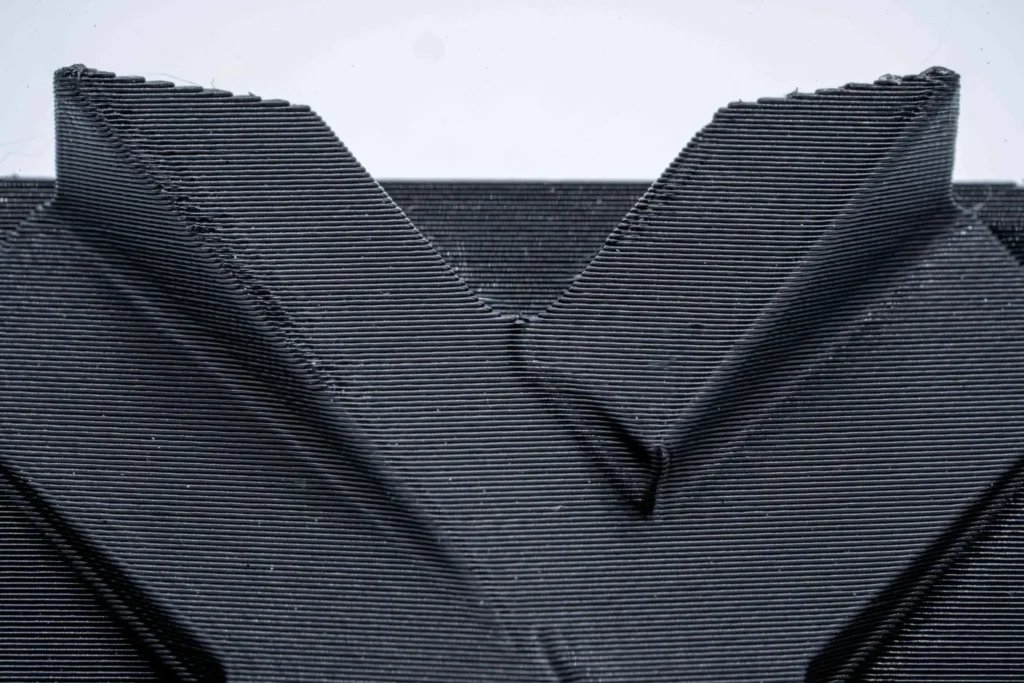
Surface Roughness for Extrusion-Based 3D Printing Processes
Fused deposition modelling (FDM) is the most common 3D printing process that belongs to this category. It works by pushing out a thermoplastic filament through a heated nozzle. The liquified thermoplastic cures one thin layer after another according to the input CAD data on the build platform, thus achieving the complete part. Support structures are needed in this technology to support the cantilevers or thin structures.
This process parts with a much higher surface roughness than other 3D printing technologies. The top layers (in Z-direction) are usually corrugated and bottom layers are smooth, provided no support structures in that region. The surfaces are pore free unlike PBF ones at the same time, not as glass like as in SLA.
In places with support material, the rough surfaces are impaired and need to be corrected in the finishing phase. A work around is the use of soluble (water or other chemicals like limonene) support materials, which are easily removable and allow for better quality.
Surface Finish Options for Extrusion-Based Processes
For very commonly used FDM materials like PLA, PA 6, the surface finish options are limited to the support structure removal, as any further operations will impact the aesthetics and details of the part and damage it. ABS can be grinded, tumbled or blasted.
It is because, even though PLA is stronger and more rigid than ABS, its poor heat resistance, poor ductility and low flexural strength properties make it tough to rework. ABS is weaker and less rigid, but also tougher and lighter, making it a better plastic to perform finishing operations.
Surface Roughness of Fused Deposition Modeling Parts
The table below details Ra and Rz values on both sides for an FDM 3D print:
| Material | Surface finish | Ra | Rz |
| ASA | As printed | 22.5 µm* | 114.9 µm |
*This result was measured on the roughest surface, perpendicular to the layering. When we measured the part’s surface in the other direction, the spin of the tool measured along with the layers and the surface roughness was 0.9 µm.
Surface Roughness for Photopolymer Droplets Technology
The most common 3D printing process in this category is Polyjet. It is a rigid photopolymer additive manufacturing technology that works by jetting UV curable resin onto a build tray in a process that is somewhat similar to inkjet printing. It is well known for its speed and incredible precision. This technology also produces support structures which are removed later in the post processing.
The surface quality is one of the best among all 3D printing technologies. One downside is the use of support structures and it impacts the related region when removed.

Surface Finish Options Photopolymer Process
If soluble support structures are used, no treatment is usually needed. If not, they need to be manually removed like in other technologies. Since it uses a deposited droplets system and the print head moves in X-Y direction, lines are visible along the movement of the print head. These can be removed in post processing for very smooth surfaces. The post-processing methods used to get improved surface quality are blasting and grinding.
Measured Surface Roughness of Polyjet 3D Printed Parts
The table below details Ra and Rz values on both sides for a Polyjet 3D print:
| Material | Surface finish | Ra | Rz |
| Photopolymer rigid | As printed | 2.1 µm | 17.2 µm |
Additive Manufacturing Processes’ Surface Roughness Compared
| Technology | Material | Surface finish | Roughness (Ra) | Roughness (Rz) |
| SLS | Alumide® / PA 12 filled with aluminium | As printed | 8 µm | 50.1 µm |
| SLS | PA 12 | Bead blasted | 4.5 µm | 31.6 µm |
| SLS | PA 11 | Dyed black | 7.5 µm | 47.6 µm |
| SLS | PA 12 | Media tumbled | 7.1 µm | 45.5 µm |
| SLS | PA 12 | Vapour polished + dyed black | 2.5 µm | 19.7 µm |
| MJF | PA 12 | As printed | 10-12 µm | 59.9-69.4 µm |
| MJF | PA 12 | Chemical vapour polished | 4.4 µm | 31.1 µm |
| MJF | PA 12 | Dyed black | 5.8 µm | 38.7 µm |
| MJF | PA 12 | Spray painted black | 5.5 µm | 37.1 µm |
| DMLS | Aluminium Al-Si10Mg | Bead blasted | 10-12 µm | 59.9-69.4 µm |
| DMLS | Stainless Steel 316L | Bead blasted | 6 µm | 39.8 µm |
| DMLS | Titan Grade 5 | Bead blasted | 5 µm | 34.4 µm |
| SLA | Industrial White, ABS-like | As printed | 1.5 µm | 10.1 µm |
| Carbon DLS | EPX 82 | As printed | 1.22 µm | 11.1 µm |
| FDM | ASA | As printed | 22.5 µm | 114.9 µm |
| Polyjet | Photopolymer rigid | As printed | 2.1 µm | 17.2 µm |
Order Parts for Your 3D Printing Projects
The 3D printing surface roughness varies greatly with post processing. It not only improves the aesthetic value but also usability of the part for end use applications. Colouring methods like spray painting and dying can also be used to enhance the surface but it’s impact on surface roughness is highly debatable.
Xometry Europe offers 3D printing services online, for on-demand additive manufacturing projects, for both prototypes and large batches. With a network of more than 2,000 partners all over Europe, Xometry is able to deliver 3D printed parts in up to 7 days. Upload your CAD files to Xometry Instant Quoting Engine to get an instant quote with various manufacturing options available for polyjet 3D printing.


 Download