Europe
  Türkiye
  United Kingdom
  Global


 0
0
The overall production cost of sheet metal operations depends on material costs and machining costs where the former occupies a major proportion. This is why nesting your parts in the file is an important step of the designing process for sheet metal projects.
What is Nesting for Sheet Metal Cutting?
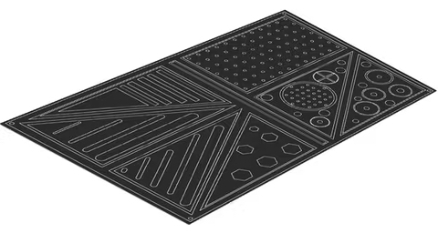
In the manufacturing context, the term “nesting” generally refers to the process of laying out multiple parts on a single sheet, thereby reducing scrap waste and optimizing production. This is widely used in the industry to reduce wastage and save costs.
A DXF file is the preferred format for our sheet cutting services. Dedicated CAD softwares can automatically nest your parts and export a DXF file for further operations.
Should You Nest Your Parts?
Before we get into the best practices, let’s take a step back and ask ourselves if we should make an effort to nest our parts. The answer to that question will mostly depend on where you come from.
For example, if you are a manufacturer, nesting files for sheet cutting are fairly standard and often required to make the most of your available material and optimize production.
From the perspective of the buyer looking to fabricate parts, it is important to remember that most sheet metal cutting shops will already have the means and familiarity with nested parts. In fact, in some cases, it can hinder the manufacturer from receiving an already nested file because it locks them into a predefined configuration that may be less than ideal.
For example, many manufacturers of sheet metal parts work with material from which parts have already been cut. It may require them to use an entirely new piece of material instead of one that they could have maxed out by nesting the pieces. Manufacturers are also more in tune with material size, machine limitations, etc.
In short, sometimes it’s easier for both parties if you send your parts as individual files. There are instances where it makes sense for a customer to nest their parts ahead of time, such as when the nested file will consume an entire sheet of material, or when the customer is supplying their own material.
The Impact of Geometry and Positioning. Practical Examples With the Instant Quoting Engine
Example 1
The choice of nesting your parts or not mostly depends on your part geometry. We will use the illustrations below to help demonstrate when nesting is a cost-saving tool and when it is not.
We have created two different DXF files with parts of the same size but arranged them differently:
- In the first file, the parts are arranged wider and occupy a larger sheet
- In the second one, they are placed side-by-side and occupy a smaller sheet
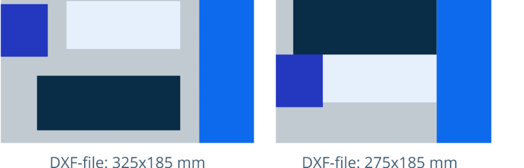
We uploaded these files to the Instant Quoting Engine (IQE) with the same parameters: material, sheet thickness, finishing etc. The algorithm recognized these two different files as identical and returned the same price:
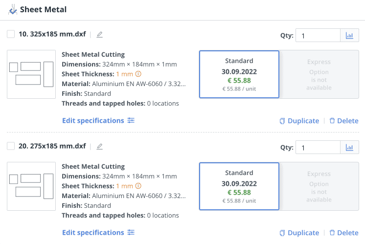
This happened because the algorithm recognizes only the “useful” space occupied by the parts. So, if you split the same parts into different files and upload them to the Instant Quoting Engine, the total price remains the same.
But it would be more convenient for the manufacturers to work with separate files. They will be able to arrange the parts themselves when setting up the equipment taking into account sheets of metal that they have.
Example 2
For the second example, we used another two different DXF files:
- In the first file the parts are arranged separately
- In the second file the bounding boxes of the same parts intersect
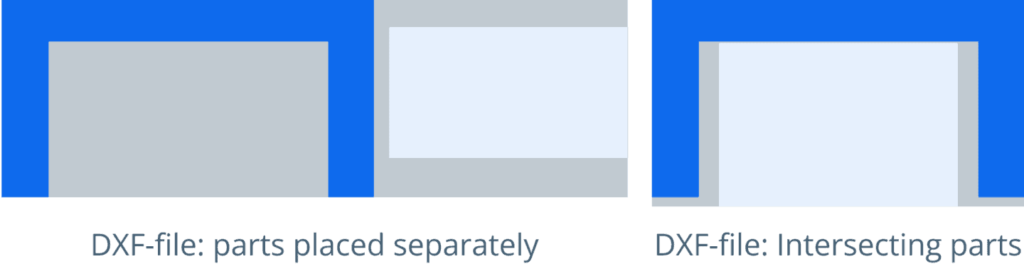
This time, the IQE recognized the files differently and gave us better price for the file in which the parts overlap:
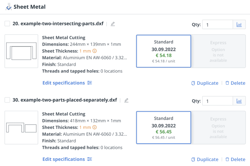
In short, if the bounding boxes of individual components cannot occupy the same space, you will get no benefit from nesting parts in the same file.
Nesting Files for Sheet Metal Cutting With Xometry
As already mentioned, the ideal method of creating nesting files for sheet metal is to use a dedicated CAD software that automatically converts the normal designs to nested DXF files. When quoting the nested parts, you should keep in mind the following advantages and considerations.
Advantages of Nesting Files:
- Get different parts quoted under one line item instead of multiple lines for multiple parts
- Avoid multiple part uploads and configurations
- Hassle-free configuration of material, finish, and other options with a single line item
Considerations of Nesting Files:
- All the nested parts must be of the same thickness, material, and finish
- Carefully nest parts according to the formal inspection as per the dimensional report. Uploading a 2D drawing for each component is advantageous for proper inspection
- A 6.5 mm margin and 0.8 mm spacing between individual parts for laser cutting
- In order to prevent the loss of small, delicate and intricate nested components, it is recommended to add breakaway tabs for pieces under 50 mm
Best Practices for Nesting Dxf Files for Sheet Metal
1. Fix Common Design Errors
It is very important to look for the potential design errors which create an unusable file that slows down the entire process of manufacturing. Costs incurred during design are minimal whereas, the costs of correction during manufacturing are way higher.
Hence, it is better to create an error-free file before sending it to quoting and manufacturing. Below are the common issues:
- Duplicating or overlapping lines, curves, points, etc.
- Unremoved information like title block information, notes, and dimensions
- Open geometry like open curves, disconnected lines, etc.
- Lines with lengths less than zero
Design tip: Export your designs as polylines to ensure that the geometry has continuous closed elements. Always ensure that non-profile elements such as titles, texts and auxiliary lines are removed.
2. Avoid Using Splines
Splines are the commonly used design features of CAD. They are used to produce complex geometries like gear profiles. The problem with CNC equipment is that they run on G-Codes and cannot read splines. They typically function on linear or circular movements.
As a result, they read splines as lines or arcs. This leads to the loss of geometric and dimensional accuracy.
Design tip: Use lines and arcs in your design wherever possible to replace splines. Export in polylines and not in splines.
3. Maintain Spacing Between the Parts
Spacing is recommended between the parts to ensure the nested parts come out as desired. This is to accommodate for the kerf or the width of the material being removed in the cutting process.
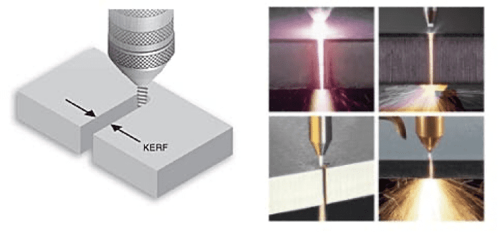
The general kerf varies based on the process, but the following guidelines are useful:
- Laser cutting kerf: 0.08 – 1 mm
- Plasma cutting kerf: 2 – 3 mm
- Waterjet cutting kerf: 0.76 –1.02 mm
4. Breakaway Tabs for Small Parts
Adding breakaway tabs for small parts or ones with intricate and delicate features help reduce loss and damage to the parts during manufacturing. They also help in keeping all the parts on the sheet after cutting, for instance, additional post processing in case of very thin material.
Design tip: It is recommended to add breakaway tabs to parts smaller than 50 mm, or for delicate features. Tabs about 0.05 mm work for most parts.
5. Optimise the Parts with Nesting Software
Using automated nesting functions or dedicated optimising software like Autodesk Fusion 360 (download the Xometry add-in) or ProNest can help squeeze the maximum parts into the available space.
These softwares are also able to fit in complex shapes which are difficult to achieve normally. It is highly recommended to export the file as DXF after the nest optimization.

Design tip: Many popular CAD softwares have a built-in nesting feature. Check if your software has it or use a software that can nest files easily.
Prepare Your CAD Files and Upload Them Online
Nesting the sheet metal parts helps in simplifying the order, material and cost reduction. Exporting a DXF nested file always makes it easy for cost estimation. Upload your files to Xometry Instant Quoting Engine and get a quote in a matter of seconds for your sheet cutting projects.

 Download