Europe
  Türkiye
  United Kingdom
  Global


 0
0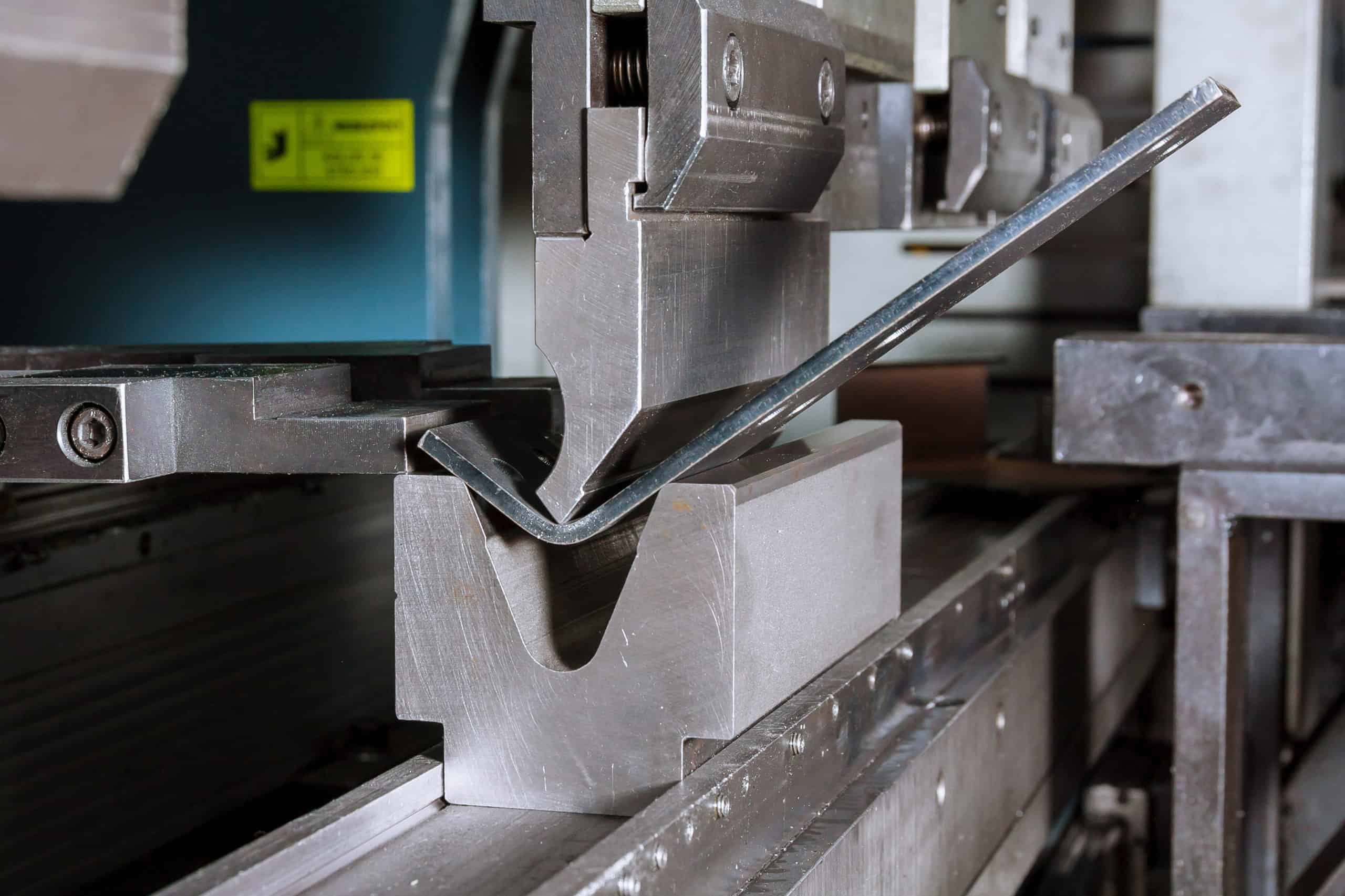
Bending is one of the most commonly used processes when forming sheet metal parts. Bending is done by holding the workpiece in position using clamps or dies and strategically applying force on an area of a workpiece. The force applied must exceed the yield strength of the material to cause the plastic deformation of the part.
This process results in a v-shape, u-shape, or channel shape over an axis, creating a new part geometry. Bending changes the shape but the volume of the workpiece remains the same.
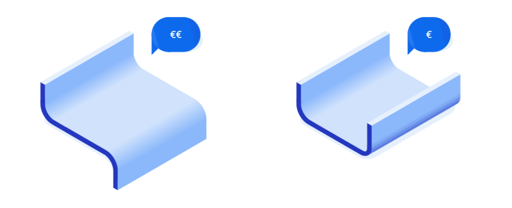
The costs and quality depend on various factors including setup costs, material costs and design complexity.
To ensure a trouble-free bend and to avoid deformation in sheet metal fabrication, we recommend following certain design tips for every type of sheet metal part feature.

Sheet Metal Design Tips for Bending
To ensure a hitch-free bend and to avoid deformation, the following 10 tips are vital when designing.
1. Walls: Uniform Thickness
Sheet metal parts are usually fabricated from a single sheet of metal, so they should have a uniform wall thickness.

2. Bends: Radius & Orientation
Keep a minimum bend radius to prevent parts from fracturing or distorting.
We typically recommend that the smallest bend radius should at least be equal to the sheet thickness.
However, there are also various reference tables that show minimum bend radii for different materials and part thicknesses.
Keeping the bend radius consistent makes the part cost effective as you can use the same tool to bend it.
Keeping bends in the same plane in one direction also helps to save time and money by preventing part reorientation—especially for sheet metal parts with complex bending.

3. Bends: Placing Bends Next to Each Other
You should avoid successive bends except where absolutely necessary. A common problem for successive bends is the difficulty of fitting the bent parts on the die. However, when unavoidable, the intermediate part should be longer than the flanges.

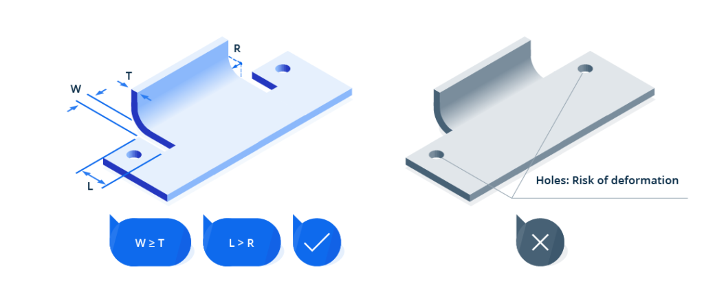
4. Bends: Cut Reliefs
When a bend is made close to an edge the material may tear unless bend relief is given. The width of the relief cuts should at least be equal to the material thickness and the length should be longer than the radius of the bend.
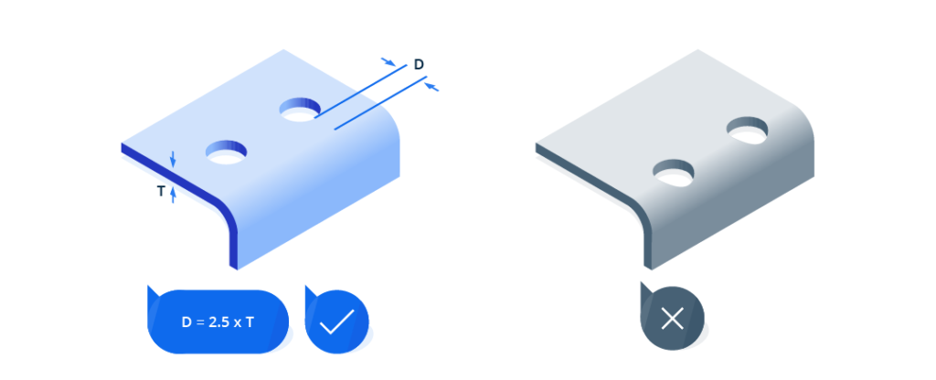
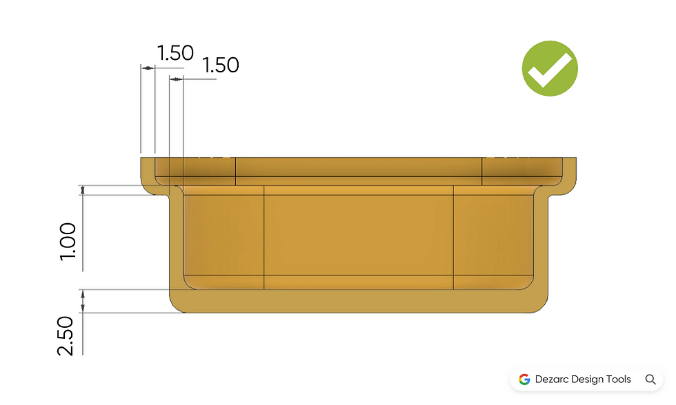
5. Holes & Slots: The Correct Clearance
Holes and slots can deform if they are too close to a bend.
We recommend placing holes at least 2.5 times the material’s thickness from the bend edges.
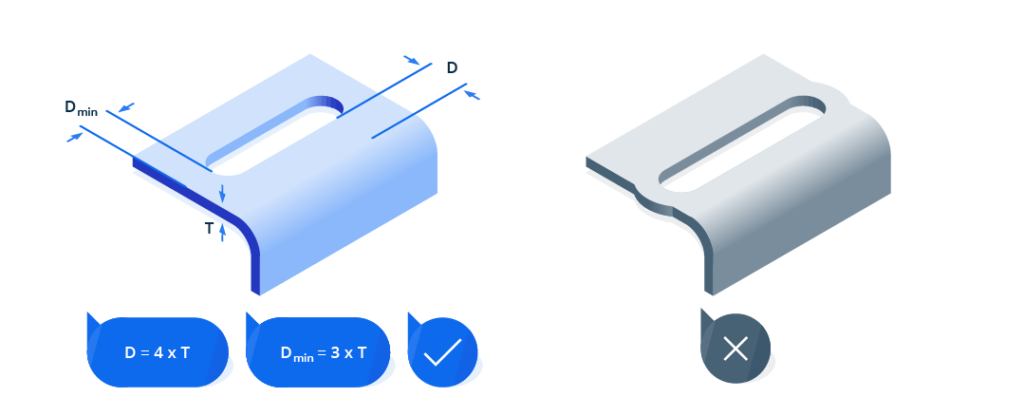
Slots require more clearance. Place them at least 4 times the material’s thickness from the bend edges.
In addition, extruding holes or slots is one of the most extreme pressure applications that creates a lot of friction and heat. To avoid deformation or tearing of the metal, place the extruded holes at least 3 times the thickness of the sheet from the edge.
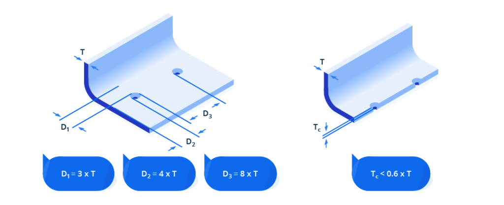
6. Countersinks: Clearance & Size
Countersinks are created with a drill press or punch press tooling.
The basic rules for countersinks are as follows:
- Keep a minimum distance of 3 times the material thickness from a bend
- 4 times from an edge
- 8 times from each other
- And they shouldn’t be deeper than 0.6 times the material thickness.
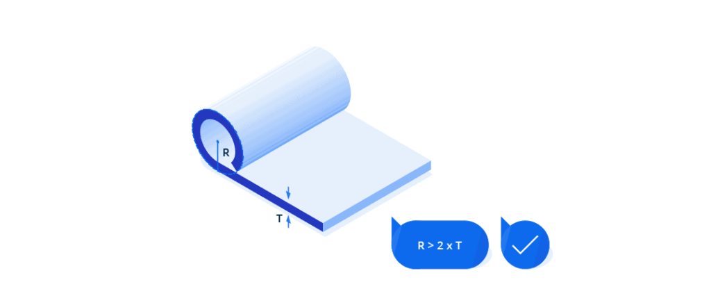
7. Curls: The Right Dimensions
Curled edges are stronger and safer for handling. They are often used to remove a sharp untreated edge and make it safe.
The outside radius of curls must be at least twice the size of the material thickness.
If you add holes next to the curls, place them at least the size of the curl radius plus the material thickness from the curls.
Other bends should be placed at least 6 times the material thickness plus the radius of the curl from the curls.
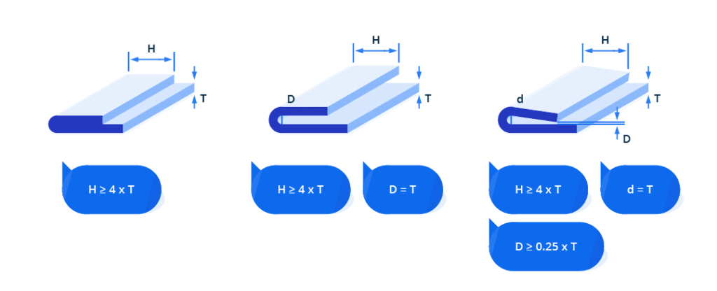
8. Hems
Sheet metal hems are often used to strengthen the edges and make sharp edges safer.
Closed hems are not recommended if they are to be painted or the part is made of stainless steel or aluminium. Their flange length from outside the bend should be equal to or greater than four times the part thickness.
The same flange length to sheet thickness ratio applies for open and teardrop hems.
For open hems, the inside diameter should be at least the same size as the sheet thickness. It will lose its roundness when the inside diameter is greater than the thickness.
For tear drop hems, the diameter should also be equal to the sheet thickness. The hem opening (spacing between the hem edge and the part) should be at least ¼ of the sheet metal thickness.
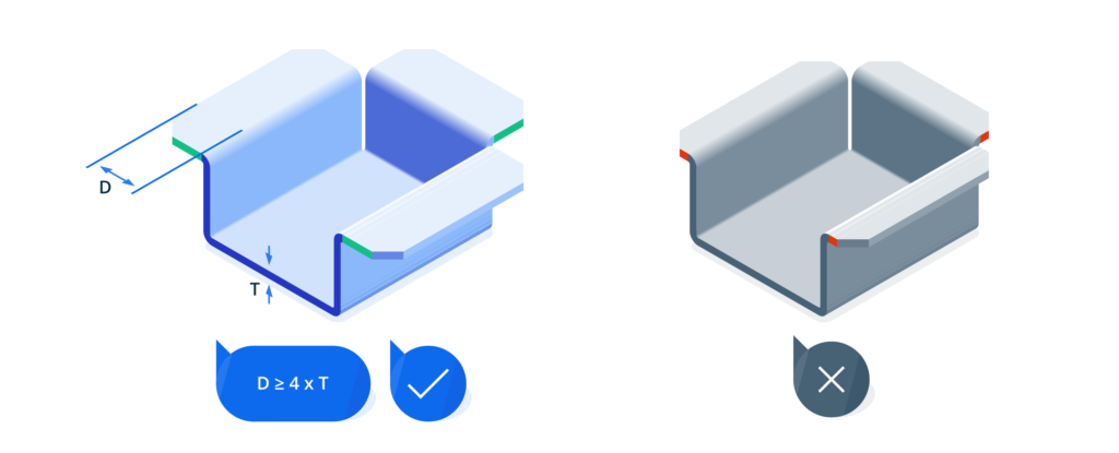
9. Flanges & Chamfers: The Right Dimensions
Flanges are the edge of the part that is bent from the stationary base. It should be at least 4 times the sheet thickness. If you make a flange with chamfered ends, these chamfers have to leave enough room to achieve proper bends.
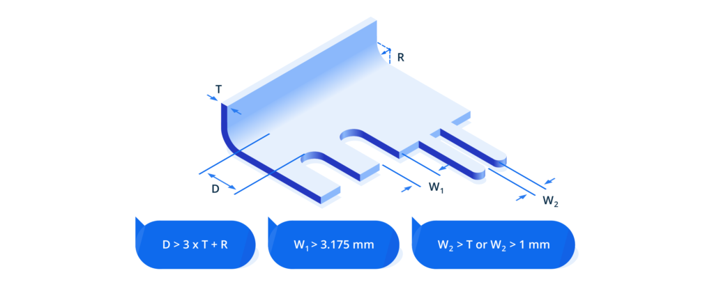
10. Tabs & Notches: Clearance
Notching is a shearing process that removes a section from the outer edge of the part. Distortion may occur if the distance between the notches and the bend is too small. To avoid this, the notch-to-bend distance should be at least 3 times the sheet thickness plus the bend radius.
Notches must be at least 3.175 mm away from each other. The minimum distance between tabs should be 1 mm or the sheet thickness whichever is greater.
Calculating Required Bending Force
Different factors are involved in creating the right bend in a sheet metal part. These include:
- Bending strength of the material
- Degree of bending
- Sheet metal thickness
- Bend angle
- Internal radius
- Vee die opening
- Minimum internal edge
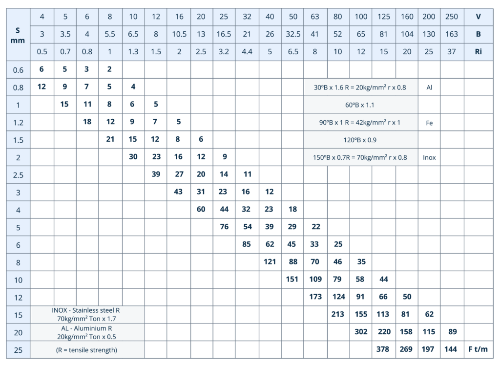
The chart below can be used to calculate the bending force required to V bend mild steel S235 of different thicknesses, in different shapes, at an angle of 90°. Mild steel S235 has a bending strength of 42 kg/mm². The variable parameters are as follows.
- S (mm) – Sheet metal thickness
- V (mm) – Vee die opening
- B (mm) – Minimum internal edge
- Ri (mm) – Internal radius
Sheet Metal Fabrication Services at Xometry
At Xometry Europe, we offer high-precision, fast, and quality sheet metal fabrication, forming and bending, services for the creation of sheet metal parts made of aluminium, stainless steel, steel, copper alloys, and many others.
Using automated bending techniques, we guarantee high precision and quality of ready sheet metal parts.
We also carry out post-processing upon your request. To get an instant quote, upload your models on our instant quoting platform.

 Download