Europe
  Türkiye
  United Kingdom
  Global


 0
0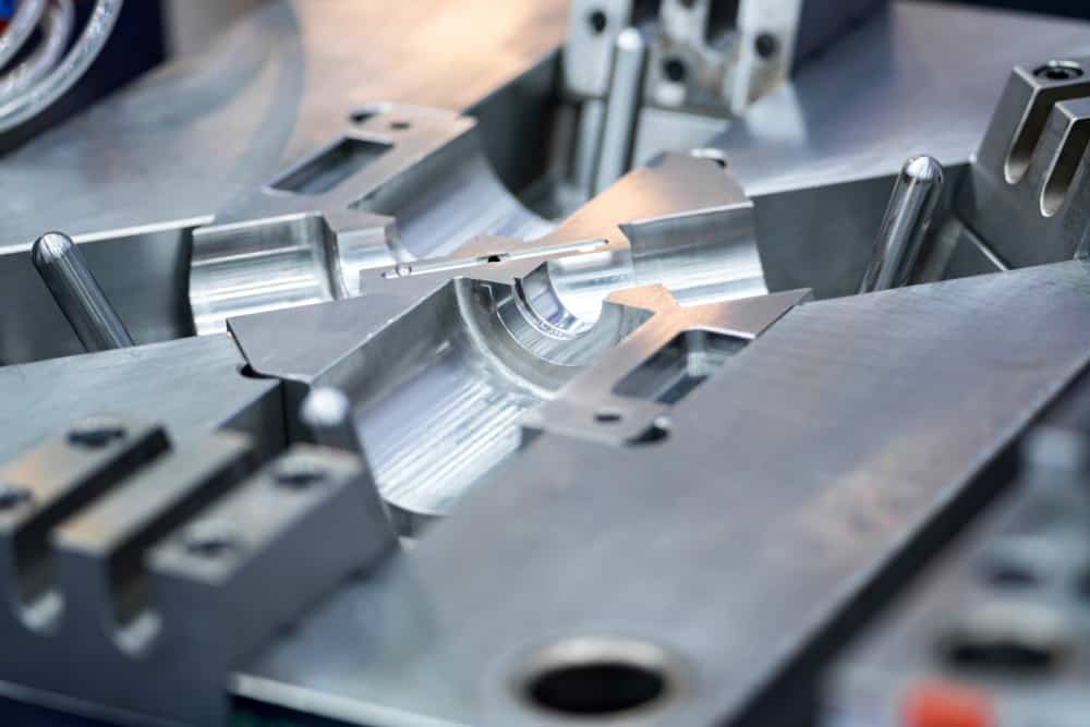
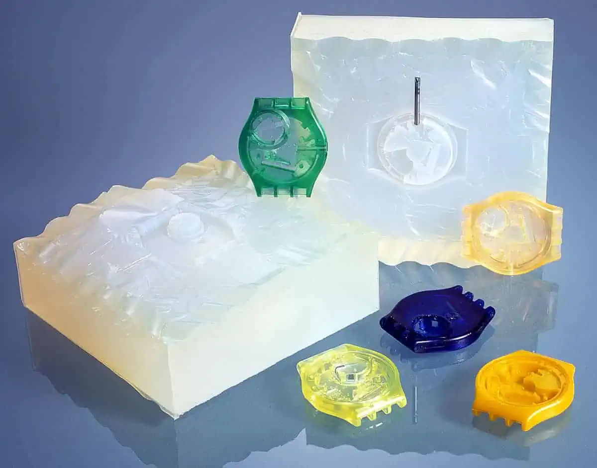
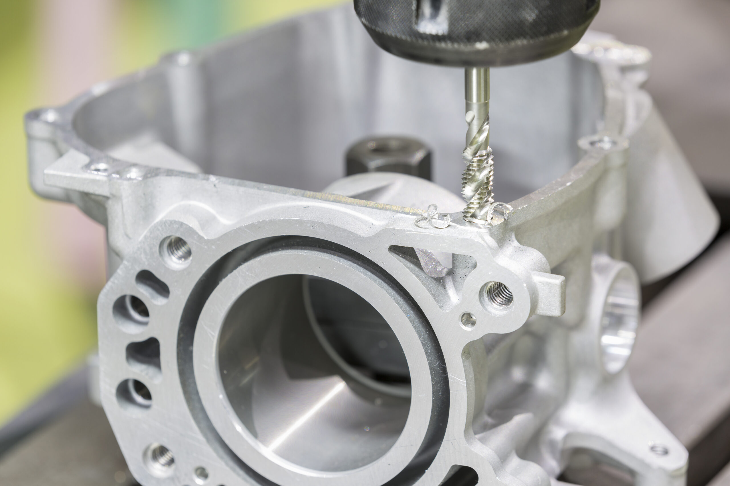
Die casting is a process where molten metal is injected into a mould under high pressure. It is used to produce parts with complex shapes that would be difficult or impossible to machine using traditional methods. Hence the importance of having a good design for your die casting projects.
Designing perfect die cast parts is about taking into account the design of the die, the type of metal being used, the production process, and the application of the final product. In other words, it’s about ensuring that every element comes together to create a functional, durable, and aesthetically pleasing piece.
In order to get the most out of die casting, designers need to follow some basic tips.
Major considerations for die casting design
While designing a perfect die cast may seem like a daunting task, it is ultimately rewarding when you see your vision come to life in an appealing and functional final product. Here are some of the things you need to keep in mind during the design process:
- The die casting process can be used with a variety of metals, including aluminium, and zinc. Each metal has its own unique properties such as fluidity and solidification, which need to be taken into account during the design process
- The die must be able to withstand the high pressures involved in the process and must be accurately machined to ensure a precise final product
- The production process needs to be taken into account when designing die castings. For example, the design may need to accommodate the use of cores or inserts
- The part should eject easily from the die without damaging the surface or leaving any flash
- The part function and intended application must be prioritized when designing die castings. For example, a die casting used in a high-stress environment will need to be designed differently than one that is purely aesthetic
Top Design Tips for Die Casting – Important Variables
There are a few key variables that you need to take into account when designing your die casting. These include:
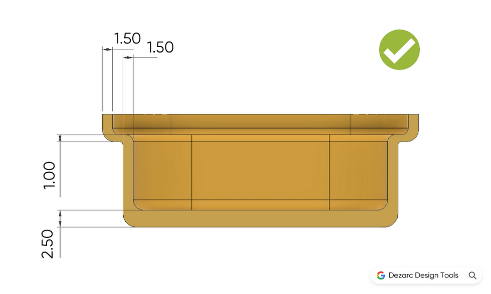
1. Fillets and Radii
In die casting, one of the most important design tips is the fillets and radii. These features help to create smooth transitions between surfaces and prevent stress concentrations. As a result, they play a vital role in ensuring the strength, aesthetics, and durability of the final product.
The size and shape of the fillets and radii will depend on the specific application, but they should not be less than 1 mm.
Inappropriate fillets and radii can affect the strength of a component by changing its cross-sectional area. So here are some design tips related to fillets and radii:
- Avoid sharp corners as they can create stress concentrations
- Use a larger radius for highly loaded areas
- Pay attention to the radius at the junction of two surfaces as it can have a big effect on the strength of the joint
- Use constant fillets and radii throughout the design to maintain the strength and smoothness of the component
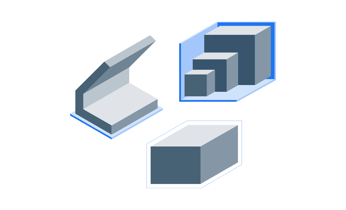
- Add draft angles to the surfaces aligned with the mould opening direction. It ensures that the component can be removed from the mould without damaging the surface. It typically ranges from 1 to 3 degrees, but it can be larger for more complex shapes

2. Wall Thickness
The wall thickness should be designed keeping in mind the desired strength, stiffness, and weight of the final product. It affects everything from the amount of time it takes to cool the cast to the amount of pressure that can be exerted on the mould.
The ideal wall thickness for a particular application depends on a number of factors, including the size and shape of the part, the materials used, and the production process.
Some of the minimum wall thicknesses for large and small castings are as below:
- Aluminium: 1.016 – 2.032 mm
- Zinc: 0.381 – 0.889 mm
- Magnesium: 1.016 – 2.54 mm
3. Ribs and External Corners
Ribs are used to reinforce the wall of a component and to increase its stiffness. They also help to distribute the load evenly and prevent warping. External corners are often used to create sharp transitions between surfaces. Both of these features need to be taken into account when designing die castings.
The thickness of the ribs and external corners will depend on the specific application. For example, thicker ribs may be needed for a component that is going to be under a lot of stress.
Some other important design tips related to ribs and external corners are:
- Ribs should be added to the thinnest wall first to prevent the component from becoming too thin
- The spacing between the ribs should be kept uniform and the external corners should be avoided if possible, to prevent stress concentrations
- If external corners are necessary, the radius should be as large as possible to reduce the stress

4. Windows and Holes
Windows and holes are often used in die castings to allow for the passage of fluids or to create a connection point between two parts. They need to be taken into account when designing the casting to ensure that they do not affect the strength or integrity of the final product.
Windows are typically located on the top or side of the mould and are generally rectangular in shape. Holes, on the other hand, can be located anywhere on the mould and come in a variety of shapes (e.g. round, square, etc.).
When designing windows and holes, it is important to keep the following in mind:
- The edge of the holes and windows should be rounded/filleted
- Holes and windows should be located away from sharp corners and edges
- Higher draft angles may be needed for windows and holes that are located on the side of the mould
- In some cases, it may be necessary to post-machine the holes and windows, but it will increase the production time and the cost
5. Post Machine Features
Some features, such as threads or undercuts, can only be created after the casting has been made. This is typically done through a process called post-machining. Post-machining is an additional step in the manufacturing process and will increase the lead time and die cast part cost. It is important to keep this in mind when designing die castings.
If post-machining is necessary, the following tips should be taken into account:
- The location of the feature should be considered to minimize the amount of material that needs to be removed
- The feature should be designed so that it can be easily and accurately machined
- The tolerances of the feature should be realistic and achievable
- In order to maintain the cost, try to add minimum post machine features to die casting parts
- Post machined features can also be added during the design phase by using cores. Cores are internal features that are created in the mould to create holes, pockets, or other features in the final casting
6. Parting Lines
The parting line is the line where the two halves of the mould meet. It is typically located on the side or top of the component. The parting line needs to be taken into account when designing die castings because it will cause a visible seam on the final product.
There are a few things to keep in mind when designing the parting line:
- The parting line should be located in a place where it will be the least visible
- Parting lines that are too thin can cause the part to shatter when it is ejected whereas; too thick parting lines can result in uneven surfaces and imperfections in the finished product
- It often exhibits flash which is an extra material that forms along the parting line. The flash can be removed in the post-processing stage

7. Surface Finishing Grades for Die Casting
After completing the casting process, the surface of the die casting will need to be finished. The type of finish will depend on the application of the final product. The product comes out from the die casting process with an as-cast surface finish.
The surface finishing is classified into different grades, the most common being:
- Grade-1 (Utility Grade)
- Grade-2 (Functional Grade)
- Grade-3 (Commercial Grade)
- Grade-4 (Consumer Grade)
- Grade-5 (Superior Grade)
| Class – 1 | Class – 2 | Class – 3 | Class – 4 | Class – 5 | |
| Grade names | Utility grade | Functional grade | Commercial grade | Consumer grade | Superior grade |
| As-Cast Finish | No cosmetic required | Spot polishing and painting | Zinc plating, electrostatic painting, and custom finishing | No-objectionable surface defect | Finish applied to the specific area in micro-inches |
| Final Products | Cast product with protective coating | Cast product with decorative coating | Structural parts for high-stress applications | Decorative parts | Gasket sections and O-ring seats |
| Finishing Quality | ⭐ | ⭐⭐ | ⭐⭐⭐ | ⭐⭐⭐⭐ | ⭐⭐⭐⭐⭐ |
You can choose the one depending on your requirements and budget. We suggest you to choose the minimum required grade if you want to maintain the part cost.
Die Casting Services by Xometry
At Xometry, we offer die casting services for a variety of applications. We work with aluminium, magnesium, and zinc alloys to create various intricate parts. You can also choose your required material grade from our die casting material selection guide.
Upload your CAD files on our Instant Quoting Engine to receive a quote and order parts. Check the design of your die casting project online and find the most cost-effective option by modifying quantities and materials instantly.

 Download